For a maker, having a flat work surface in the workshop is essential. But granite or cast‑iron reference plates are total overkill. Flat plywood is hard to find, and MDF, the larger the sheet, the easier it bends. So I started thinking about alternative options. Extruded aluminium works perfectly for these purposes because it offers factory‑level precision sufficient for a hobby workshop while still being relatively lightweight. In addition, it has T‑slots that can come in handy from time to time.
A 30 mm profile format seemed the most suitable for me. It has a 30 mm pitch, a thickness of 15 mm, and a width of 120 mm. To assemble a surface with dimensions of 900 mm × 600 mm, I need five pieces of this profile, each 900 mm long, running lengthwise, and two pieces 600 mm long that will connect them crosswise. I found a company that cut a longer bar of 6000 mm into the required sizes. The quality could be better, but we work with what we have.
Now for the main problem. The crosswise and lengthwise pieces need to be fastened together into a single, continuous surface so that they lie flat in the same plane. All existing solutions of this type require destructive manipulation of the profile. If you use T‑nut inserts, you have to drill through the opposite profile sections to reach the screws. And if you use clamping elements, the screws can leave permanent dents, which prevent further micro‑adjustments because the screw will always fall into the old dent, pulling the construction back into an incorrect position.
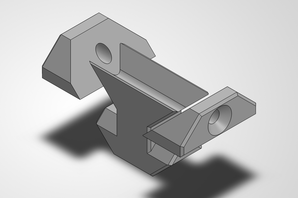
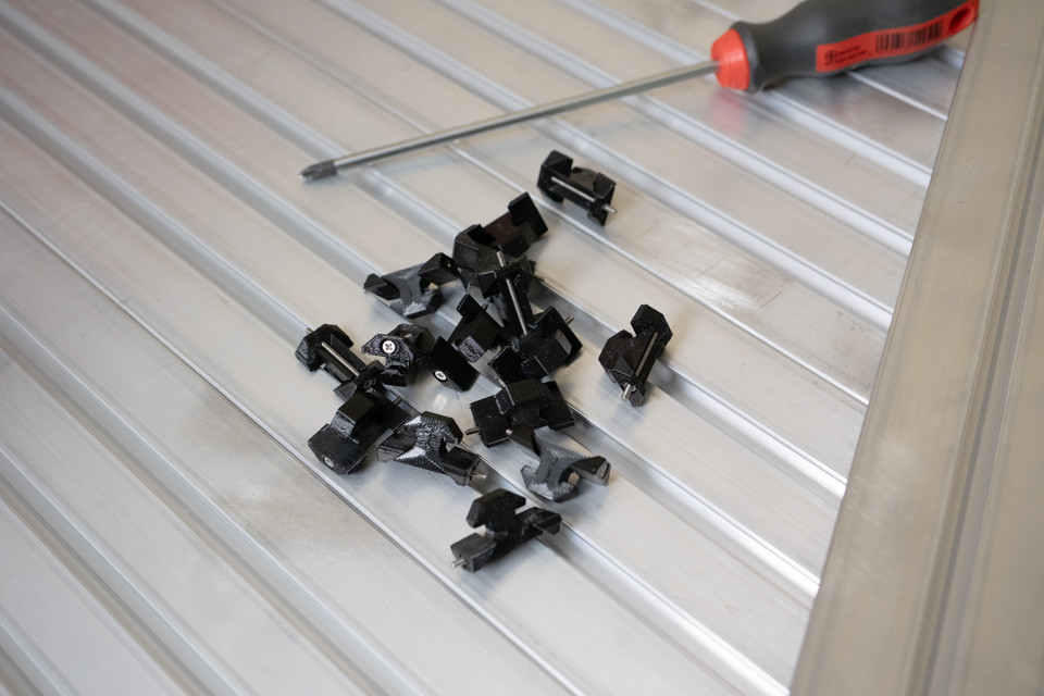
So I decided to design my own solution that can be 3D printed. This isn’t the first time I’ve investigated a combination of metal and 3D printed parts, and here is another good opportunity. This is the first version of this custom connection, and it is fully parametric. In the example you can see a demo for a 30 mm step profile with an 8 mm T‑slot.
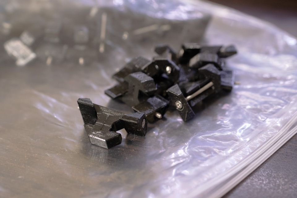
I took my time to assemble 40+ of these fastening elements... But during blackouts after the ruzzian strikes I had plenty of time, so...
The construction is fairly simple. The central part has a T‑slot shape on one end that fits into a T‑slot on the profile that will be pulled to another one. On the other end it has a swallow‑tail shape at a 45‑degree angle. A screw passes through this swallow‑tail. Two additional parts are located on the ends of the screw: one on the head of the screw and one on its nut. In one plane these parts form opposite halves that clamp the swallow‑tail. In the other plane they have the same T‑slot shape that inserts into the T‑slot on the profile that will pull the other one.
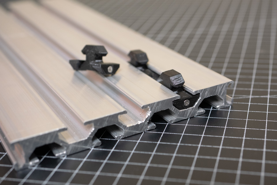
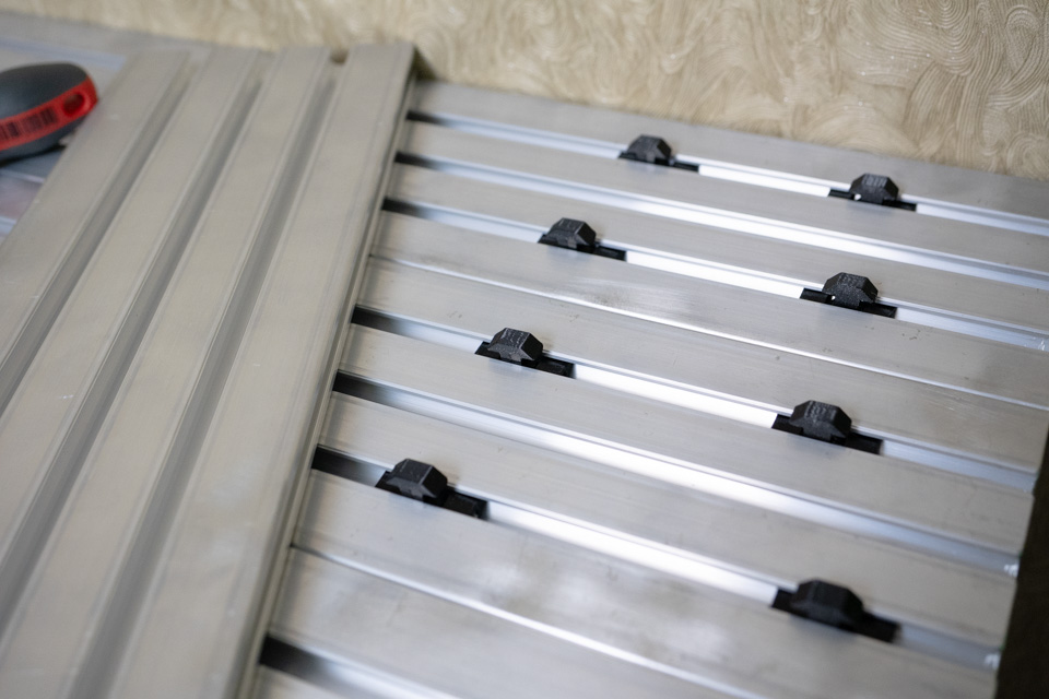
So how it works. The assembled fastening element, in its loosened state, is inserted into the T‑slot of a static profile. The protruding T‑shaped portion goes into the T‑slot of the profile that will be pulled. When the screw is tightened, the two opposing small parts pull toward each other, reducing the space for the swallow‑tail. This causes the central part to be pulled deeper into the T‑slot. Because it is hooked with the dynamic part of the profile, it pulls that part in as well. Thus, the tighter the screw is tightened, the more one profile part presses against the other.
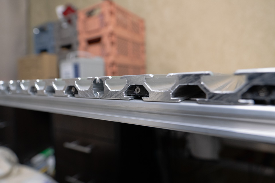
Below are a few photos I took during the assembly. I hope it will make more clear if something is not still.
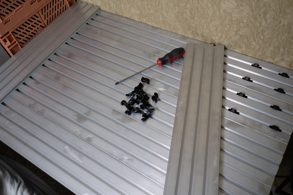
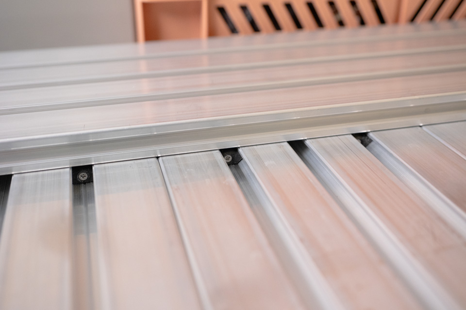
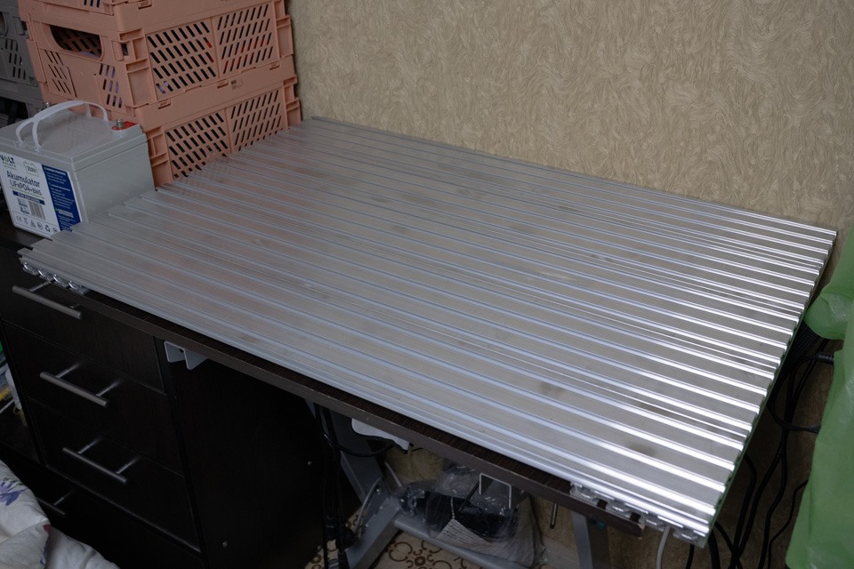
In theory, the finished surface is as flat as the profile parts themselves because they are aligning with each other. The five 900 mm pieces define the flatness along the X‑axis, and the two 600 mm pieces align them and define the flatness along the Y‑axis. The tightening elements do not merely fix the position of the parts; they pull the pieces together via the T‑slot as far as the material of the tightening elements allows. In my case the result is better than MDF, plywood, or any other countertop, but still worse than specialized assembly surfaces. It has ~0.05 mm sag in the middle, likely due to how the original profile was manufactured or stored.
And here is the result.
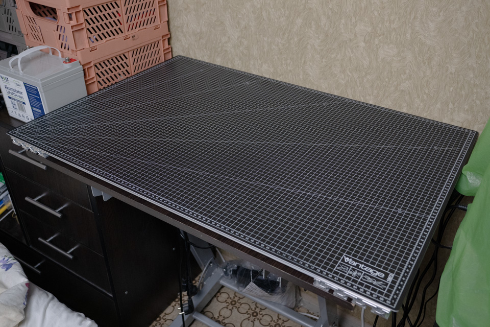
And with cutting mat cover...
Anyway, I’m very proud of how these fastening elements turned out. Here are the
.stl files for this particular example.
I will add parametric model once it will be polished.
Version: 2026_12_16_000001
Created by TennojiM
All rights reserved
© 2025
All rights reserved
© 2025